Wednesday, July 13, 2011

How I built a logic probe

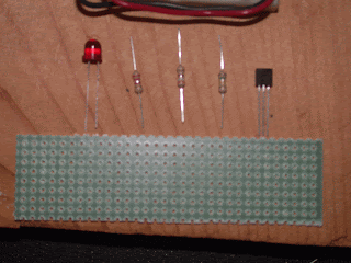
Today I built a logic probe.  I followed the handout from Prof. Mason's Mechatronics class entitiled "Build a Logic Probe".  These are the components:
This is the probe touching +5 volts (logical 1, TRUE).  The LED is bright.
 
This is the logic probe touching nothing.  The LED glows dimly..
 
 Here the probe touches 0 volts (logical 0, FALSE, common, ground).  The LED is dark.

 Bottom view of the assembled probe.  A drop of hot glue was added later to hold the power clips to the board.  The probe is made from a paper clip.


 Top view of the assembled probe.
Monday, January 31, 2011

Color Sensor Breadboard Test

The video shows a breadboard with a PicAxe 14M interfaced to a color sensor.  The pattern of the two orange LEDs changes according to the color of the paper placed over the detector.